

|
|
 Mystique
Features and Patents |
|
HOME Site Map Contact Us Except where stated this site is in no way affiliated with any of the products or companies mentioned or depicted within except as noted |
This page puts the spotlight on some of the Gilson snowblower features I consider noteworthy. I'll include some in the context of how we sold machines based on these features. Gilson also had a number of patented snowblower design features and I'll share those as well. Sources tell me that Gilson held nearly 20 patents across their power equipment lines, I have identified about half that number. They paint a picture of an innovative company that dared to be different.
Mystique...... interesting choice of words some of you may say as you look at what may now be a weathered somewhat rusty piece of vintage power equipment. After all the newest Gilson machines are now about 20 years old as of 2008 and they go back at least 42 years at his time. I'll ask you to remember that I placed several hundred of these machines into service throughout the 1970s. When I think of a model in my minds eye I see if factory fresh just coming out of the carton with the smell of fresh enamel and ready for final assembly. I remember the enthusiasm with which we sold these machines and the customers we pleased. Some machines that have found their way into my collection I learned were machines I set-up when they were new. Sometimes it's a small world.
By the 1970s Gilson had 2 distinct lines of full sized snowblowers. By full sized I'm referring to machines in the 8 HP or bigger class. There were the Gear Drive machines, which were being sold by 1966. The second line was the UniTrol or friction drive machine, which were introduced in 1970. Along the way there were also smaller machines including the Snow Cannon, one of the first of the 2 stroke lightweight machines that seem to gain popularity every year. To make sense of this I'll deal with the Gear Drives and then the UniTrols, intermediate and finally the compact machines.
I went on to have a career engineering production automation so machines have been a big part of my life. This reminds me of an episode of Star Trek The Next Generation, #130, "Relics" in which Scotty from the original series and Captain Picard discus their first starships, it goes like this, "It's like the first time you fall in love... you don't ever love a woman quite the way you did that first one".
Enjoy the page.
If I had to describe a Gilson Gear Drive in one word it would be "TANK". If you have read my History of the Gilson Brand
page you know that the company's roots are in the foundry industry. This heritage is in full view in these machines, especially those built up to the mid 70s. Skids, chute bases, auger main bearing supports and the auger worm drive case were all cast iron components. Elsewhere on the machines there was heavy gauge steel and more welds than many competing machines ever dream of. Many of the designs held stable from 1966 until then end of the company in 1988 and especially after 1972 when the 3 speed sealed Peerless transmission was introduced.
The term "Gear Drive" caused a little bit of confusion since belts and chains were still employed. The one thing these machines did not have was a friction wheel, the rubber wheel common to Gilson's UniTrols and nearly every snowblower traction drive system built today. The speed selections were derived from the cog system shown in the REVERSING TRANSMISSIONS feature below. By shifting the cog shown near the top of the pictures 1 of 2 drive ratios could be chosen and the speed was the same for forward and reverse. The gearboxes shown provided the reversing function. In 1972 nearly all of the components you see in the bottom of the machine were replaced with a sealed Peerless brand 700 series transmission that provided 3 forward speeds and a reverse. Also in 1972 the machine was widened from 26 to 28 inches and a visor was added to raise the front opening. In the final years the Peerless unit was upgraded to a 5 speed model. During the 70s a 32 inch version was created and it was latter upgraded to a 10HP Engine supplied by Tecumseh since Briggs & Stratton did not have a winter engine to fit the application.
The pictures below include some details of the auger assemblies. The captions detail some changes that occurred in the early years of the model family. The auger shafts are 1 inch in diameter and ride in spherical bushings with Zerk fittings. In these pictures you can see the cast iron bushing sockets that support it all. The auger leads were heavy gauge and deep, the outboard tips were braced and the leads were securely welded to the support tubes. The actual gearcase was based on the legendary Gilson garden tillers.
In latter years the case was changed to die cast aluminum alloy and the design of the side cover was changed for ease of assembly and service. The unit continued to be a durable design.
One selling point was that the chutes were round with no corners for snow to collect in. We were perplexed when the design changed to a squared chute around 1977. In my opinion the squared chute lets the stream spread out too much and reduces throwing distance.
In practice, it is common to leave the drive belt engaged while shifting. When running under constant power be sure to pause in neutral when shifting to forward or reverse. This will avoid subjecting the transmission to the force of full torque reversal.
In all modes it is important to move into Forward or Reverse without hesitation. This transmission is not designed to be gently engaged. If you try to feather engagement you will increase wear of the engaging features of the bevel gears.
The "UniTrol" Machines
These were friction drive machines. A friction drive machine uses a spinning platter and a rubber tire to select speed and direction. By running the wheel in different places on the platter different ground seeds are selected. Move further from the center and since each revolution has more circumference more speed is transferred. Move across the center of the platter and the direction reverses. This concept was nothing new, a 1915 patent depicts for this system being used as an automobile transmission. See U.S. patent # 1,133,690 & 1,147,268.
The existing snowblower application of this system required the use of 2 controls. One to lift the friction wheel clear of the platter and a second one to change and set the position for speed and direction. Gilson engineers designed a control system that did it all with one lever and it worked slick. As I did for the gear drives if I had to pick one word to describe these machines it would be ELEGANT. The system is detailed in U.S. patent # 3,678,770. The term "UniTrol" was coined by the marketing manager.
One interesting feature that I have not found cited in the patent is that when a friction wheel wears down it will hit the axle before the steel core collides with the machined drive platter. This warning if heeded can prevent most platter damage.
When you look at a UniTrol control and drive system you see a collection of pins, yokes rods and bellcranks that embody a very specific set of functions. Shifting can be done by holding the control lightly between your thumb and forefinger. The system was very attractive to customers who did not care for the heft of the geardrive machines. Overall the machines were a little lighter in construction using alternatives to the castings found on the gear drives. The difference in selling price was generally less that 10% when compared to the competing gear drive.
The most common version of these machines was the 8 HP. As Gilsons they were built as 5,8 and latter also as 10 HP machines. All the same except engine and tires. On private brands such as Montgomery Ward many were built with 7 HP engines and these were with either semi pneumatic or hard rubber tires. All "Gilson" 8 and 10 HP machines got fully pneumatic tires. These afforded better traction and held up much better over time. They are also easily replaced to this date.
Introduced in 1970 the machine was built through 1979 with the biggest modifications being the addition of safety interlocks, an impeller pulley brake and taller tires in the 5 and 10 HP machines. About half way through the run the Gilson color scheme changed from crimson and beige to crimson and black.
It was replaced with an entirely different friction drive transmission that delivered 5 forward speeds and 2 reverse. The handles were of a tubualr design making the change in generation very obvious. The blower and chute portions of the machine however continued the classic design.
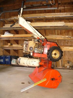
With the fuel tank less than 1/3 full it can also serve as a stand when servicing components on the bottom of the machine. CAUTION: heavy use can cause the drift cutter to bend above where it bolts to the machine. If the bar is distorted it may not safely support your machine. If this is the case replace or repair the bar by straightening and reinforcing. Replacements are available here.
The following U.S. patents are cited on this page:
The Intermediate Machines
The Compact Machines
So that's how the product line went for a little more than 2 decades. We're always on the lookout for pieces of the puzzle so if you have any information or documents you'd care to share I'd be delighted to hear from you. Thanks again to the many Friends of the Snowblower Shop that have helped augment my experiences with correspondence and materials.
The Gilson Snowblower Shop Home
Page created 1/11/04 ***** September 20, 2021
The "Gear Drive" Machines
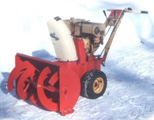
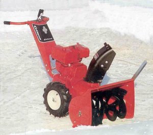
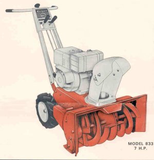
This is the machine that started it all. This is a model 835 from 1969. The design was introduced at least as early as 1966. On my gallery page you can see my Montgomery Ward branded GIL-478A from 1966. These machines include all of the heavyweight features outlined below. Many of these machines were sold under numerous brands. The series continued until 1972 when model 55012 shown at the end of this feature was introduced. I've taken in 10 of these in various brands, horsepower's and ages.
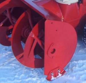
This is the side view of the gear drive bucket. Note the cast iron skids, massive auger shaft bushing supports and the no nonsense welded steel plate construction. Note the vertical leading edge of the bucket side. The auger leads actually reach out ahead of the machine. The advantage here is that the machine did not need to push the dead side plate into a snow bank in order to digest it. They transitioned to the full rounded profile midyear in 1970 with model 5002. That profile can be seen below on model 55012.
REVERSING TRANSMISSIONS (GEAR DRIVE MODELS)


The earliest 2 stage gear drive machines used this reversing transmission. These transmissions were built by Gilson. Functionally they are quite similar to the Foote unit shown on the right. Overall I'd consider them to be a little simpler. They are of cast iron construnction where the Footes have aluminum housings. I only have 1 of these in service. I have seen them in use in machines built from 1966 - 1968. Repair parts support for these has lapsed. Here is a breakdown of this transmission.
On later machines a FOOTE transmission was used. According to the Foote manual they were used from 1969 to 1972. They were Series 35 units models 35-9 and 35-26. The Foote parts manual shows no apparent difference between the two models. The Gilson parts price list says to use #16053 in the 13840 listing, these are the Gilson numbers for these transmissions. Foote is now part of DANA and they no longer support these.
Here is a breakdown of this transmission. On the Parts Page you can find shifting forks, input and output bushings, clutch collars and bevel gears. Most other parts I can supply as good used parts, just e-mail me about what you need.
GEAR DRIVE AUGER LEAD SUPPORTS

The supports that connect the auger leads (the helical bands) to the center tube were made from two opposing pieces on the earliest gear drive models such as my GIL-478A this design was also used on the 1968 production of model #835.
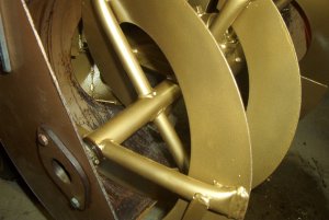
On later machines a continuous tube was used and it was contoured and welded to flow across the center tube. With the exception of my GIL-478A all of my gear drives are of this configuration. My 1969 model 835 is shown in this photo.
This photo shows the worm drive assembly. It employs a steel worm gear and a brass worm wheel to reduce the speed and to make the 90-degree transition. The cast iron case held everything in precise alignment. The input shaft is supported on large tapered roller bearings and the bearing fit is adjustable with the cast nut at the front of the case. There is a level check plug in the front and a vented fill plug at the top of the case. With the machine on level ground it should be filled up to the level check plug. This is an oil filled case that uses SAE 30 non detergent oil. Also note how far back the gearcase extends giving the high-speed shaft lots of support. Compare this to most of today's models.


Here is a view of the chute used on the gear drives for many years. The base is a cast iron ring gear and it is turned by a pinion gear controlled by the hand crank. The assembly is held down by 3 brass rollers riding on dog screws. It makes the full 190 degree swing in just over 3 turns of the hand crank. This is real handy when doing a back and forth pattern requiring frequent redirection of the discharge. The downside is that the chute will drift from some positions if you don't keep a fingertip on the crank handle. Clean it off and butter it up with good grease annually.
The foundation of the gear drive machines is this base weldment. All of the walls are of 10 gauge steel and welded throughout. The heavy 1/4 inch thick handle mounting horns are an integral part of the weldment and with Gilson's structural handle towers made for an exceptionally sturdy assembly. This handle design got finalized on the UniTrols and then rolled back into the gear drives and is highlighted in the Unitrol segment of this page. As I said, built like a tank, complete with armor.


These are the handlebar controls on the 26-inch gear drive machines. One lever controls a belt idler that applies power to the traction system. The other lever shifts the constant mesh transmission from neutral to forward or dead man reverse. The manual calls for disengaging the drive belt before moving the transmission selector. There are also a few rare 22-inch versions of this design.
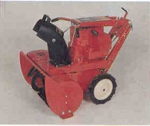
This is model 55012, in my opinion the most over the top tank of a machine ever built. The model saw refinements and a reduction in cast iron over the years but remained a heavyweight until the end. Introduced in 1972 it had an 8 HP Briggs and Stratton engine and cut a 28-inch path. No need for tire chains on this beauty. Traction came from a 3 speed Peerless 700 series transmission.


UniTrol Control & Transmission

![]()
Here is the control console, the motion is smooth and there is affirmative feedback as the transmission engages, The reverse has a "deadman" function that requires the operator to keep pressure on the control lever. If the operator should slip and fall while in reverse the machine will stop moving.
This is the transmission area. You can see the platter at the bottom driven with an integral pulley. The friction wheel intersects at a right angle. The friction wheel is carried on a hexagonal shaft that transfers power to a double reduction set of final drive gears located in the housing to the left.
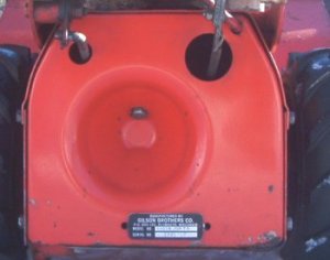
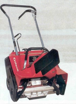
This is the back panel of a UniTrol model. The large concave depression is a signature feature. Most of these machines were 3 speed models but there were a few made that had 4 speed selections. Also note the location of the ID tag or sticker at the bottom.
In designing the UniTrol machines engineers took the existing Gilson handle concept of welded unified assembly one step further. Rather than 2 rails they formed a 7 sided steel tower and integrated all of the control components. This provided a rigid control station and a sleek appearance. The steel tower concept was omitted from the last generation of machines however they did remain welded assemblies. This design concept is evident in today's machines from Simplicity.

Model 55134 introduced in 1977 was the pinnacle of the UniTrol machines. With a set of taller tires ground clearance was better and the ground speeds also increased nicely. This was most appreciated in reverse, which had been a very conservative speed. Several refinements made over the prior 7 years made for a proven trouble free machine. It also had a 5 HP sister with smaller tires and another with a 10HP Tecumseh engine all on the same platform. This platform was probably the most widely sold Gilson snowblower with versions going to Montgomery Ward, LawnBoy and Ford among others.
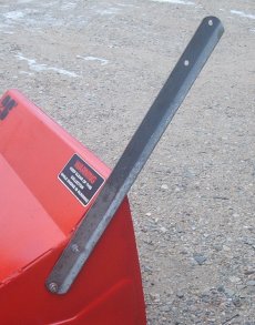
Most machines came with a drift cutter to help twitch tall drifts down for clean-up.

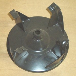
The UniTrol Impeller design was awarded U.S. Patent number 3,736,674 for it's extensive use of stuctural details to add strength. Components were embossed, cone shaped and interlocked for extra strength.
Examining patents can be a lot of fun. Whether on this topic or nearly any other. Ever wonder what makes something special when you see a patent number on a product? Here's how to view the patent and see for yourself. Since patents reference the patents of prior art is can quickly become a history lesson.
From here I'll leave it up to you to create advanced searches and to follow cited patents. Do remember that patents from 1790 through 1975 are searchable only by Patent Number and Current US Classification!
If you want to do some research and follow names and terms here are some guidelines.
If you would rather not deal with the patent office's kludgy interface you can also search for patents as well as call them up from number using the patent feature Google provides.
This is one of the original designs. These single stage machines ran from 1966 to 1970. The handle design has continuity through the line. This single stage bucket was also the basis for the first generation of tractor attachments that were sold through the mid 70s. The machines were discontinued just as Gilsons became widely distributed here in northern New England. I have yet to see one in person but I do hear about them frequently in my email. Someday I'll snag one somehow.
These intermediate 2 stage machines were introduced in the early 1970s and ran through the decade. They were introduced as 18 inch 4 horsepower and latter were grown to 24 inch machines with 5 horsepower engines. They were single speed machines with forward and reverse. The friction drive transmission was protected by U.S. patents 3,813,954 & 3,720,112. To keep the units compact in size and to make them economical the engineers developed a design that did not require the traditional "fire wall" behind the impeller. Instead they integrated the impeller and lower blower pulley and a labyrinth seal to the chassis. This effectively kept the snow out of the traction transmission area. You can learn more about this by viewing U.S. patent #3,774,322.


This is machine is from the final generation of Gilson machines. Introduced around 1980 they had 5 forward speeds and 2 reverse. The bucket and chute assemblies are from the single speed machines in the above picture. This generation of machines is based on U.S. patent # 4,457,086 and included some interesting design concepts that have been heavily referenced by competitors in subsequent years. One is that the friction wheel slides across the platter but instead of lifting the friction wheel to allow shifting the drive platter actually tips away to create a gap. There are also full sized versions of this machine that replaced the 3 speed UniTrol.
This is what Gilson branded as the "SNOW CANNON" It was one of the first of the rubber flight 2 stroke machines on the market when introduced in the late 1970s. A 32:1 two stroke fuel mix is required. The chute simply deflected the snow by diverting the stream in the selected direction. In this picture snow will move through the black deflector but also up the right hand side of it as it leaves the collector. The initial models were built with the first of the Briggs & Stratton 2 stroke engines, a dual first. Later machines had Tecumseh engines and as well as OMC power plants. They used the term TURBO-THRUST to describe the throwing action but it did not seem to be trademarked. Being small enough to ship by UPS these show up often on EBAY branded as Gilson, LawnBoy, Montgomery Ward and Ford. You can learn more of the story behind these machines in U.S. patents 4,214,767 & 4,203,237. These patents are still being cited in current inventions. Common parts to renew your Snow Cannon can be found here.

This was billed as "The Machine That's Fun to Run" when introduced in the late 1970s. It's a single stage 20 inch machine with forward only traction, the operator pulls it backwards. If one word described this machine it would have to be COMPACT followed closely by RADICAL. Size drove the decision to use a vertical shaft engine since with a horizontal shaft power has to zig zag it's way down through the power train. In this design it is transmitted to where it is needed and then goes straight down. Since this style engine was not available as a winter engine Gilson had to provide the engine shrouding. The drive arrangement including construction of the right angle gearcase is detailed in U.S. patent # 4,123,857. This patent has been cited in a wide range of applications. A novel pulley mounting method was registered under U.S. patent # 4,016,770.
Common cable methods of control linkages allowed for machines to fold as shown here. One exception was chute rotation where shaft transmitted torque was the norm. Gilson engineers came up with a crank and cable system that allowed the folding of the handle as shown here. It's detailed in U.S. patent # 4,068,397. The folding handle was based on Gilson tiller design patent # 3,744,322.
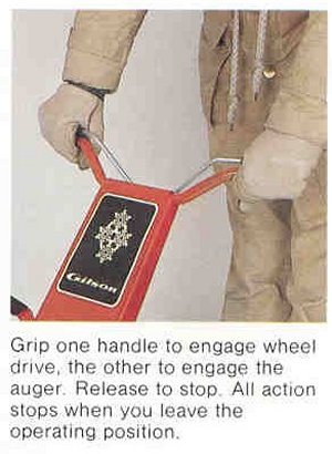
Along with the Snow Cannon this was one of the first machines designed with modern safety measures. The 2 clutch levers controlled power to the drive and blower segments. No switches or wires except a key switch for security lockout. This prevented a lot of nuisance engine stops. I have also seen these as Montgomery Ward branded units.